The above image shows the powerline (it should not dip towards gnd).
Home >Class April 11 Assignment
actually most of what i learned today was about recovering from a wrong fuse setting.
i made the dc-motor board, and as it didn't appear to be working right away, i looked at the makefile and saw that it contained a make-fuse option.
and without questioning i put the fuse command to the board.
Afer the first syn error from avr-dud i immedeately knew what the problem was, but by then it was too late already. As i was underway home already i did not have the option to just change the chip. So i searched online for tips on recovering from wrong fuse settings for AVR and immedeately found this site. As i did have other (still programmable) boards laying around i chose the board wit the led and the button to act as my 'revivor' board.
I changed the program a bit, and added extra settings to the avrdude command line.
int main(void)
{
    CLKPR = (1 << CLKPCE);
    CLKPR = 0;
    DDRA = 0xFF;

    while (1)
    {
        PINA = (1 << PA4);
    }
}
> avrdude -p t44 -c usbtiny -U lfuse:w:0x6a:m -U hfuse:w:0xdf:m -U efuse:w:0xff:m -B 100 -F -V -e
I attached the power pin from the led/button board to the power input on the H-bridge board and the clk pin (which now generated a nice 4MHz square wave) with a smd-test-clip directly to pin2 (XTAL1/CLKI).
next i ran the avr-dude program a few times until it 'took' (until i saw it programming) then i removed the clock-lead and cycled the power and then i was able to reprogram my board :)
As a note on throwing pins on a port up and down as fast as possible:
    asm volatile("ldi r16, 16"             "\n" \
                 "start: " "out 0x19, r16" "\n\t" \
                 "rjmp start"                     \
                 :  : );
is exactly as fast as
    while (1)
    {
        PINA = (1 << PA4);
    }
but the following needs an extra cycle (both previous examples need 3)
    while (1)
    {
        PORTA = ~PINA;
    }
So maximum clock attainable this way (using a 20Mhz resonator) is 3.33Mhz (or 2.0 Mhz in the last example)
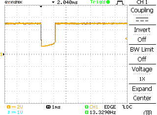
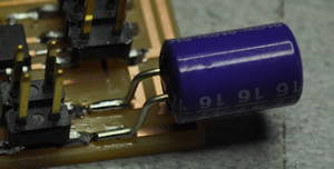
Other trouble included that the tiny44 seems to short itself out with the start load of the motor.
The above image shows the powerline (it should not dip towards gnd).
As it turned out, the board worked fine on a battery. This got me suspicious of the powerlines. So after looking at the incoming powerline i noticed this:
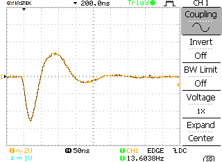
So after adding a 47uF Cap over the supply lines the problem was solved.
Soo thereafter though i did some sloppy programming, with as result a smoked h-bridge
I also adapted the code to run forward, stop, backward and stop again for 1 second each.
//
//
// hello.H-bridge.45.c
//
// H-bridge hello-world
//
// Neil Gershenfeld
// 11/13/10
//
// Adapted by BasW
// 04/18/12
//
// (c) Massachusetts Institute of Technology 2010
// Permission granted for experimental and personal use;
// license for commercial sale available from MIT.
//

#include <avr/io.h>
#include <util/delay.h>

#define output(directions,pin) (directions |= pin) // set port direction for output
#define set(port,pin) (port |= pin) // set port pin
#define clear(port,pin) (port &= (~pin)) // clear port pin
#define pin_test(pins,pin) (pins & pin) // test for port pin
#define bit_test(byte,bit) (byte & (1 << bit)) // test for bit set

#define gate_delay() _delay_us(5) // delay between switching gates
#define on_delay() _delay_us(1) // PWM on time
#define fast_off_delay() _delay_us(1) // PWM fast off time
#define medium_off_delay() _delay_us(10) // PWM medium off time
#define slow_off_delay() _delay_us(20) // PWM slow off time
#define PWM_count 10000 // number of PWM cycles
#define cycle_count 5 // number of speed cycles

#define MOSFET_port PORTA // MOSFET port
#define MOSFET_direction DDRA // MOSFET direction
#define GRP (1 << PA0) // right PMOSFET gate
#define GRN (1 << PA1) // right NMOSFET gate
#define GLN (1 << PA2) // left NMOSFET gate
#define GLP (1 << PA3) // left PMOSFET gate

void clearGates( void );
void mBreak(void);
void mForward(void);
void mBackward(void);

int main(void) {
   // set clock divider to /1
   CLKPR = (1 << CLKPCE);
   CLKPR = 0; //(0 << CLKPS3) | (0 << CLKPS2) | (0 << CLKPS1) | (0 << CLKPS0);

    // initialize H-bridge pins on braking
    clear(MOSFET_port, (GRP|GLP|GRN|GLN));
    output(MOSFET_direction, GRP|GLP|GRN|GLN);
    set(MOSFET_port, (GRN|GLN));

    // main loop
    while (1) {
        mForward();
        _delay_ms(1000);
        mBreak();
        _delay_ms(1000);
        mBackward();
        _delay_ms(1000);
        mBreak();
        _delay_ms(1000);
    }

}

void clearGates( void ) {
    MOSFET_port &= ~(GRN|GRP|GLN|GLP);
    gate_delay();
}

void mBreak(void) {
    clearGates();
    set(MOSFET_port, (GRN|GLN));
}

void mForward(void) {
    clearGates();
    set(MOSFET_port, (GRP|GLN));
}
void mBackward(void) {
    clearGates();
    set(MOSFET_port, (GLP|GRN));
}
h-bridge-interface (right size images are in the archive)