 As i'm doing this for a living, this should not be a problem. I have some prior work online at the fablab-amsterdam website. (link to scottie)
Home >Class Feb 27 Assignment
As i'm doing this for a living, this should not be a problem. I have some prior work online at the fablab-amsterdam website. (link to scottie)
For this class i had a couple of ideas:
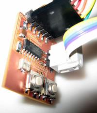
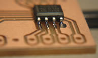
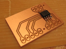
In the end I did not manage to get everything done, but I did redesign the Hello-world board to include a reset-switch and a led. (picture to the side) <design-files>

The first bord will take it's input from the color of the led on the lifesize mic, or sit in bitween the lifesize-mic and the lifesize-unit (2.5mm plug 4-poles). Using that input it will mute or unmute the blanced-phantom-powered mic that we use for recording.
I needed to find out what pin goes where , and (more importantly) figure out if there is a way to find out what state the led's/microphone are/is in.
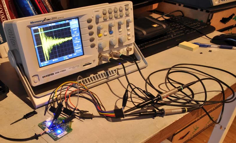
I'm going to use the oscilloscope to discover what each pin does. To accomplish this i first needed access to the board itself.
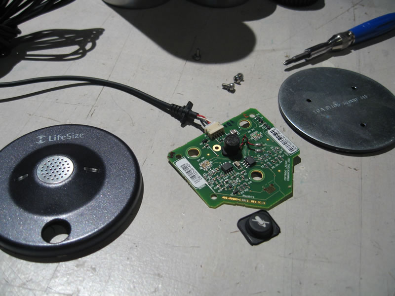
If you turn the microphone over, you discover 3 screws in the back of the device. After I unscrewed these i got the following:
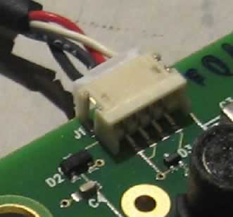
The four pins on the connector seem to match the four pins on the jack, but on closer inspection I discovered that the first two pins are connected to ground. The other two, white and red, are apparantly signal carreing wires. So now it is time to connect the o-scope.
First i need to configure the scope, and because i don't know what i'm going to find I set both channels on the scope to DC and to 2 Volts per division. I chose these settings because i don't expect really high voltages. The time per division is not really importent right now so i left that as i found it.
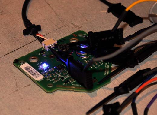
as i connected the leads and powerd the microphone i needed to adjust the scope settings a little, but after this i found the following:
| Pin Number |
Pin Name |
Description | |
| 1 | Tip | 5-15V (5V - muted/red-led / 10V - not in use/off / 15V - not muted/blue led) (red wire) | |
| 2 | Ring 1 | Not Connected | |
| 3 | Ring 2 | Microphone (biased, pulled to ground with the mute-button)(white wire) | |
| 4 | Sleeve | Ground (black wire) |
To switch from talk to mute, the microphone bias is pulled to ground the led's are off if the voltage is 10V on the red wire
I'm using an opto-coupled SSR to switch a resistor in (and out) of the balanced lines of the recording microphone (following this example)
What the circuit needs to do is enable the microphone when the voltage is at 15 volts. A simple voltage-comparator (like this, buy) would suffice. (hey, a controller-less board :P)
The second board has an i2c input, a power regulator (3.3V) for the downstream applications and an I2C port expander on every output-stream of the I2C-switch. This board will be used to attach 16 I2C RFID readers to a single microcontroller (the RFID-readers have address switches for a possible 4 address variations, hence the need for the I2C channel splitter)
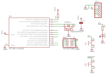
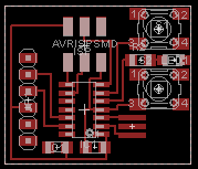
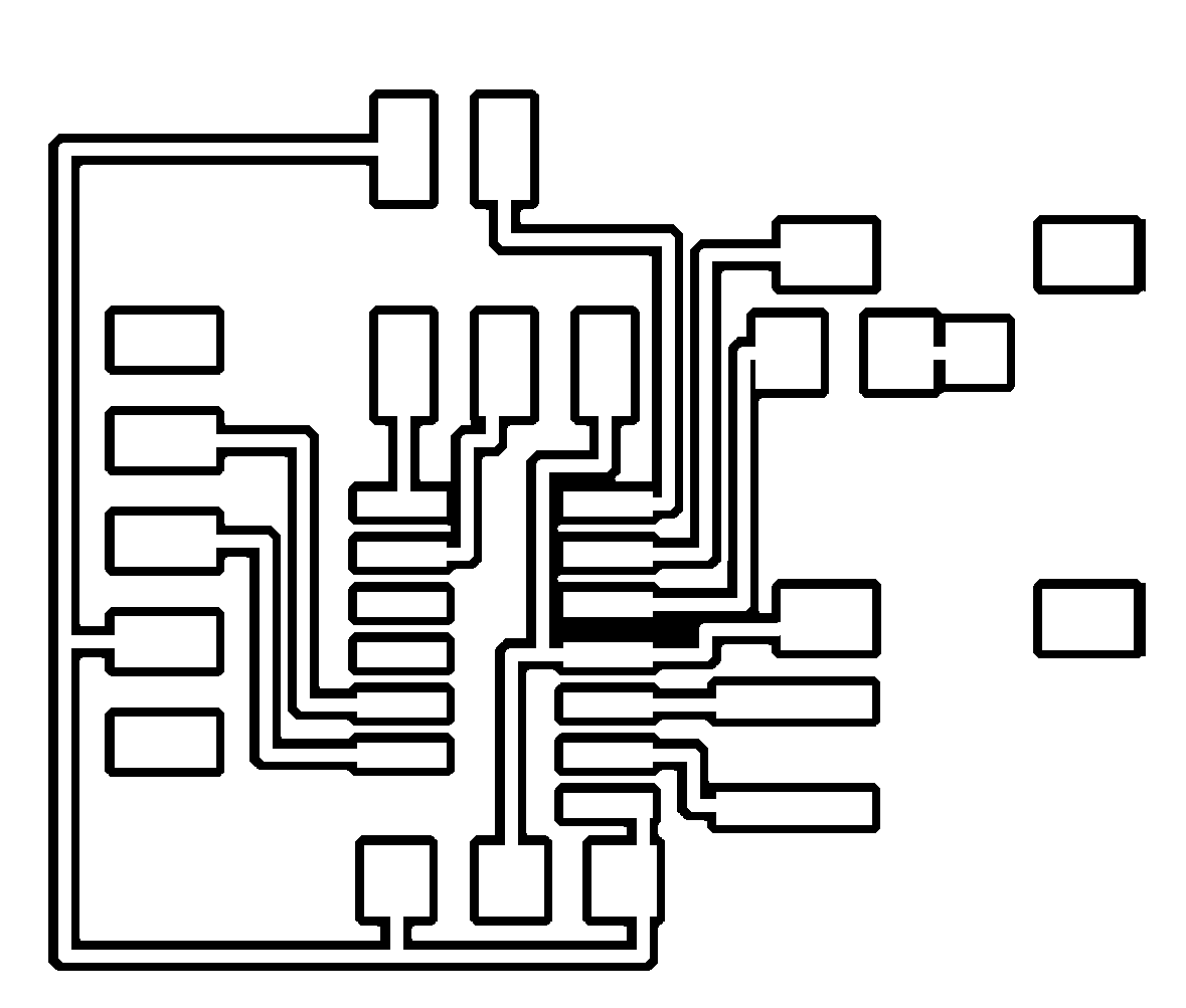
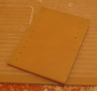
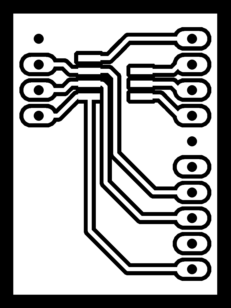
i2c expander breakout board: <sch> <brd> <outlines> <board> <finished>