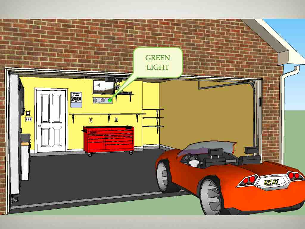
Using Google SketchUp (downlaod)
My semester project, EZ IN, is a device that will help you park your car inside your home garage. The idea is that EZ IN, acts like
a stop light. If you are far away from the front wall, you get a green light, if you get closer to the wall you get a yellow light,and once you get to the exact position you want to park, the light turns red.
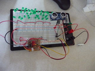
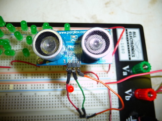
No more guessing where to park.Prototype the project using a protoboard
First to make sure all the wiring and power distribution and power consumption was accounted for, I used a protoboard. I designed the control board using (Eagle) and connected 42 LEDs (green, red and yellow) and tested the code using a (PING) ultrasound sensor.
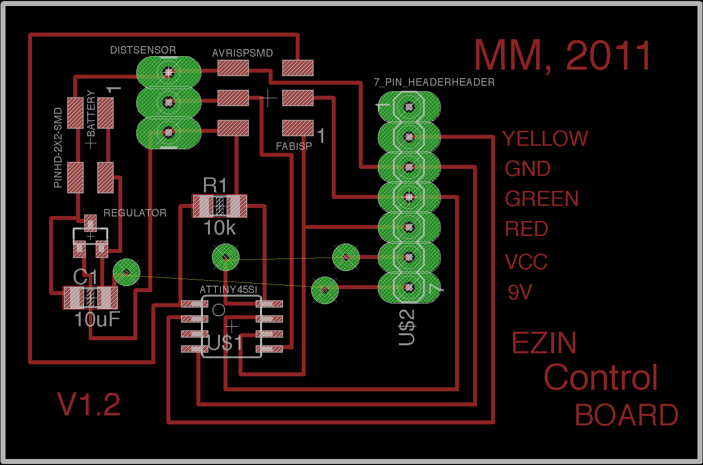
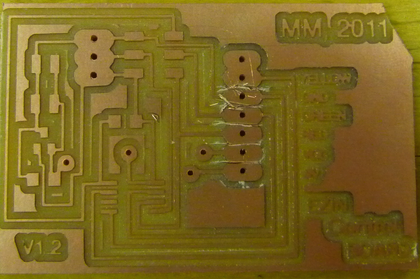
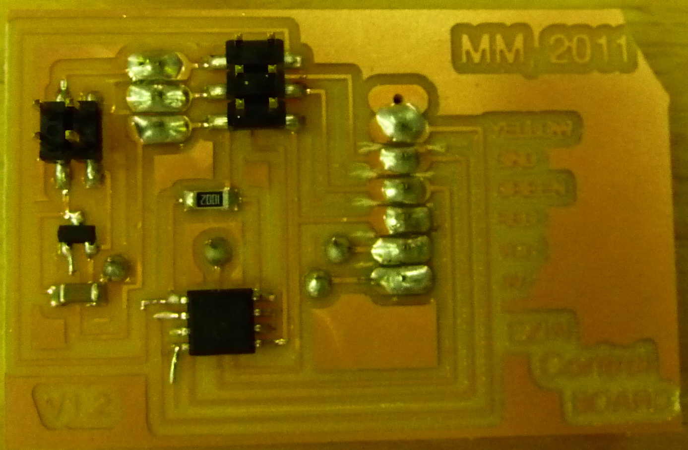
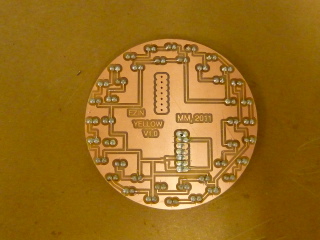
Control Board and Ultrasound Sensor
The control board is meant to connect to the red LED board and to it I also connect the PING ultrasound sensor.
I decided to make 3 boards, one for each of the transition stages, red, yellow and green.
Eagle files
 The ultrasound sensor was choosen because it was available in a very nice package, and I already had one.
Specifications:
20 mA power cosumption
Power requirements: +5 VDC
Communication:Positive TTL pulse
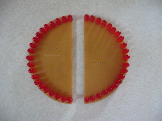
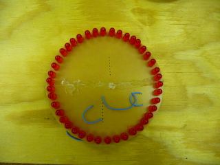
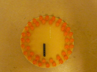
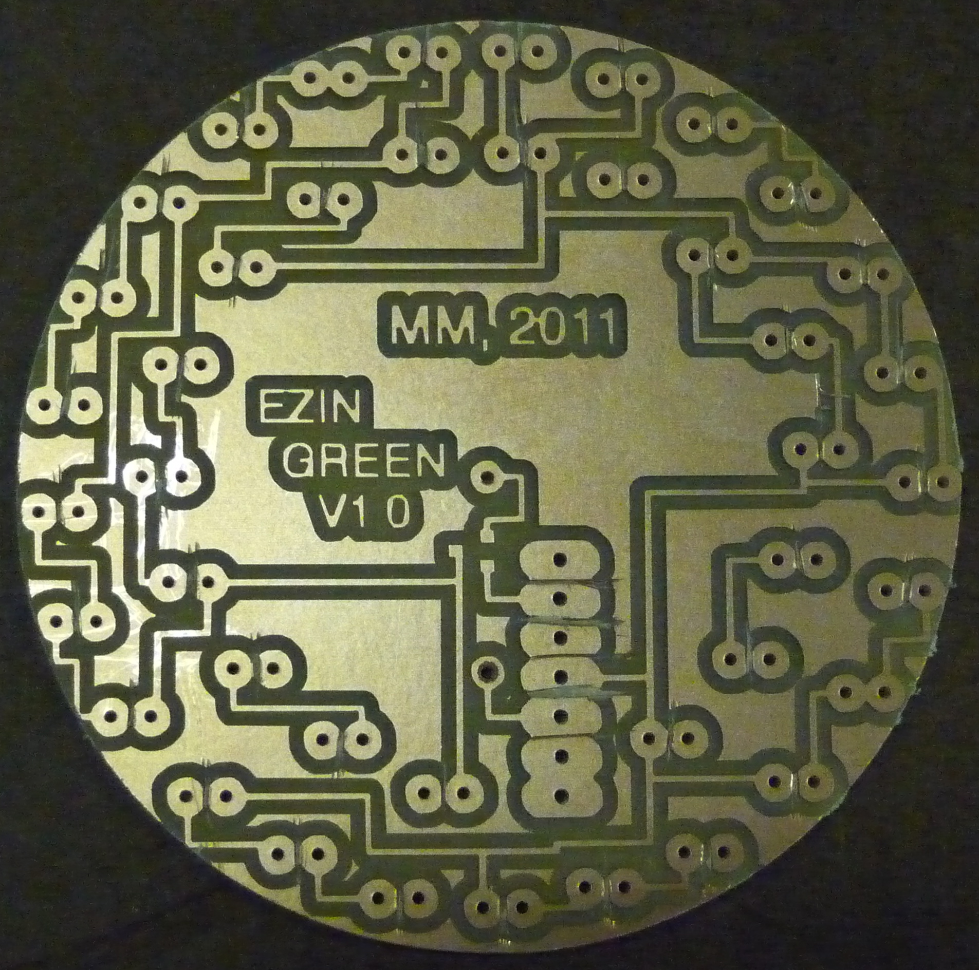
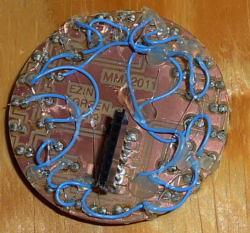
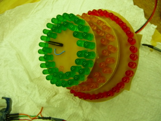
LED boards
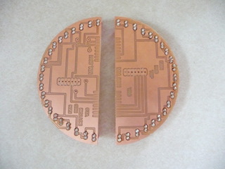
I decided to make 3 boards, one for each transition stages, red, yellow and green. The red board did not fit on a single 3"x4" cupper board so I had to
make two layout, top and buttom and attach them together with headers.
Each board has 42 leds. They are setup as 3 leds in series (3 Vdc drop on each led) and 14 parallel sets. They are swithed on and off via an NPN
mosfet (1.7A max current), the gate of the mosfet is attached to one of the pins of the attiyn45. There are 3 mosfets, one for each color led set.
RED
YELLOW
GREEN
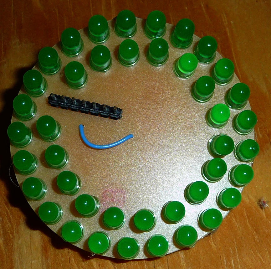
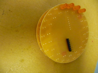
EZIN final assembly
EZIN Programming using Arduino Duemilanove
I used the Arduino board to program the attiny 45.
First I programmed the Arduino Duemilanove to be an ISP, following this step-by-step
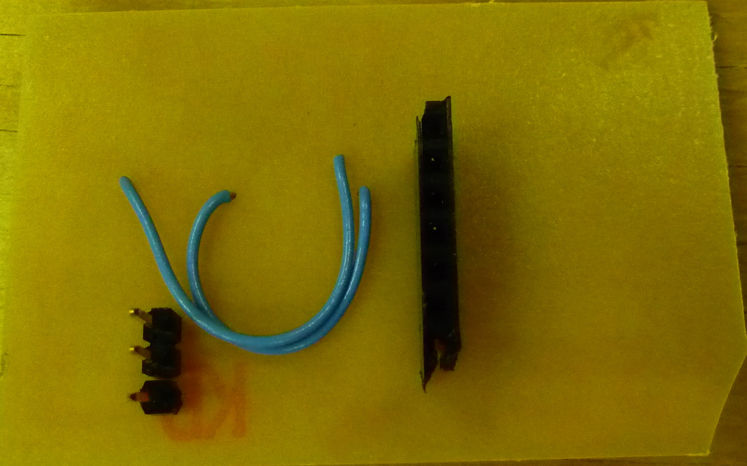
I then made the cable below to connect the EZIN control board to the arduino 2009.
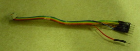 ATtiny Pin 2 to Arduino Pin 13 (SCK)
ATtiny Pin 1 to Arduino Pin 12 (MISO)
ATtiny Pin 0 to Arduino Pin 11 (MOSI)
ATtiny Pin Reset to Arduino Pin 10 (Reset)
ATtiny Pin VCC to Arduino Pin 5V (Vcc)
ATtiny Pin GND to Arduino Pin GND (GND)
Programming Files
ATtiny Pin 2 to Arduino Pin 13 (SCK)
ATtiny Pin 1 to Arduino Pin 12 (MISO)
ATtiny Pin 0 to Arduino Pin 11 (MOSI)
ATtiny Pin Reset to Arduino Pin 10 (Reset)
ATtiny Pin VCC to Arduino Pin 5V (Vcc)
ATtiny Pin GND to Arduino Pin GND (GND)
Programming Files
YELLOW
GREEN
EZIN final assembly
EZIN Programming using Arduino Duemilanove
I used the Arduino board to program the attiny 45.
First I programmed the Arduino Duemilanove to be an ISP, following this step-by-step
I then made the cable below to connect the EZIN control board to the arduino 2009.
ATtiny Pin 2 to Arduino Pin 13 (SCK)
ATtiny Pin 1 to Arduino Pin 12 (MISO)
ATtiny Pin 0 to Arduino Pin 11 (MOSI)
ATtiny Pin Reset to Arduino Pin 10 (Reset)
ATtiny Pin VCC to Arduino Pin 5V (Vcc)
ATtiny Pin GND to Arduino Pin GND (GND)
Programming Files
ATtiny Pin 2 to Arduino Pin 13 (SCK)
ATtiny Pin 1 to Arduino Pin 12 (MISO)
ATtiny Pin 0 to Arduino Pin 11 (MOSI)
ATtiny Pin Reset to Arduino Pin 10 (Reset)
ATtiny Pin VCC to Arduino Pin 5V (Vcc)
ATtiny Pin GND to Arduino Pin GND (GND)
Programming Files