Design a FabISP Board using Eagle and then Program it.
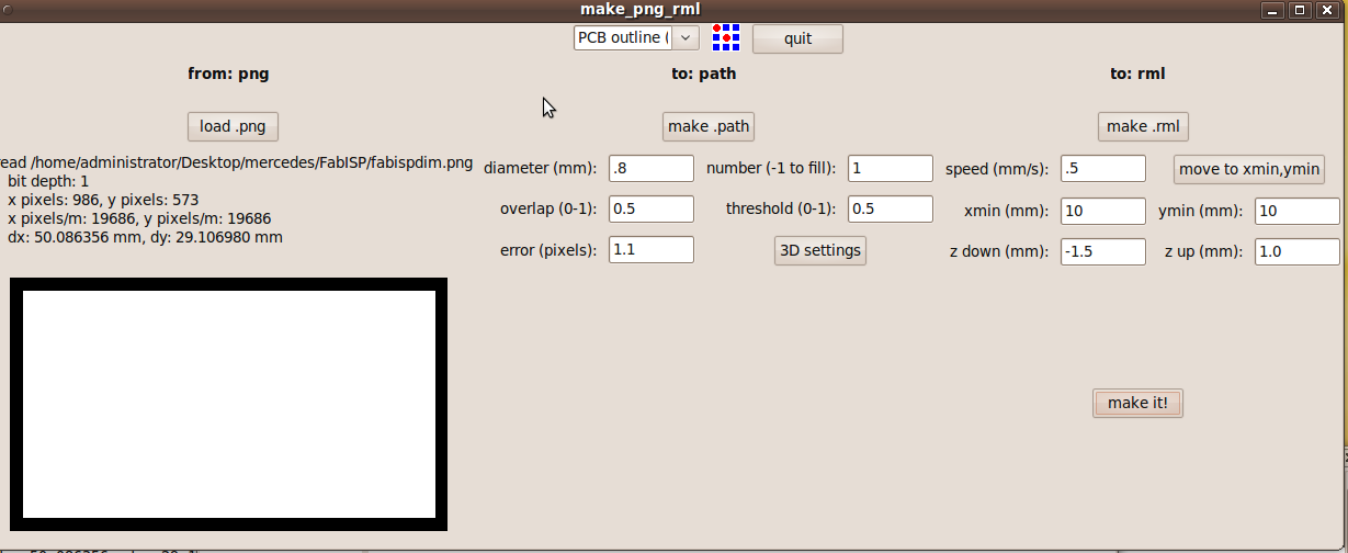
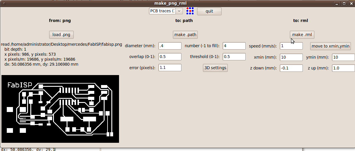
The Fab Academy project this week was to take the MIT fab module software, copy it over to the Modela MDX-20 where we were to cut out a circuit board by using the provided png image of the ISP from the fab archives. The fab module had already rendered it into a tool path so it could be output to the Modela. It took around 40 minutes to cut out my board.
To design the board I used the Eagle software that can be downloaded free off the internet.
I used the Fab Academy Website's Eagle Resources at:
http://academy.cba.mit.edu/tutorials/eagle/eagle_resources.html#links I collected my materials which were shown on the FabISP plan and began to solder them to the board. This was my first attempt at soldering EVER. I discovered I needed a magnifying glass and strong light to read the small print and fine lines. It took me hours to solder everything on to the board in their correct places since I found out my hands shake a great deal. Everything was so small it took a great deal of patience. Several times I resorted to using Dean Rose's binocular dissecting microscope to help me see the fine markings and check my placement. I did not give up and now have my work station set up correctly. I am very proud of my boards and they have passed Mercede's inspection. The FabISP board allows me to program the microcontrollers on other boards we will make, using a USB cable and 6-pin IDC to 6-pin IDC cable. ( Note: I used avrdude to do the programming.) >When I was ready to program plugged the Fab ISP into my computer using a USB cable.
I had a green light so my header was soldered correctly and getting power. I plugged aseparate pogramer plugged into the 6-pin programming header. ( ATAVRISP2)
On my computer I opened the ﺻmakefileﺽ using TextEdit and made sure I had selected the correct oscillator (12MHz) and correct ISP:
Then I entered:
F_CPU = 12000000
AVRDUDE = avrdude -c usbtiny -p $(DEVICE) --- if you are using the FABISP
I saved the file, then opened the command window and navigated to the directory where the firmware files was saved.
In the command window I typed:
In the terminal window I typed (pressing the enter key after each command block shown:)
make clean
Then type:
make hex
Then type:
make fuse
Then I typed:
make program
For Programming the FabISP board use:
Programs and Files used:
For Designing and Cutting the FabISP board use:
Eagle files: FabISP.sch, FabISP.brd, FabISP.lbr, FabLab.dru, Partslist
Software: Firmware.zip, FabModules
Modela:
Use: 1/64in bit for cutting the trace
Use: 1/16in bit for cutting the board outline.
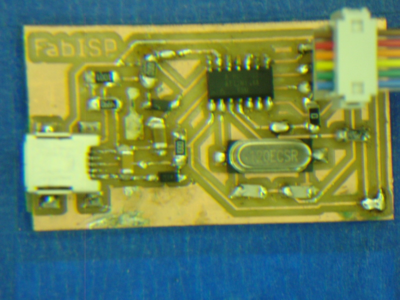
FabISP Board:
The FabISP board allows me to program the microcontrollers on other boards we will make, using a USB cable and 6-pin IDC to 6-pin IDC cable.
I used avrdude to do the programming.
I made sure that I washed the board after cutting the traces with soap. I did not use the flux but I used solder wick when I needed to remove board parts to resolder them back on correctly. My biggest challenge was seeing the components I was soldering on the mini USB connector. (It was difficult to see where the fine leads were, and if I was getting the solder placed correctly.