For my assignment this week I wanted to control 2 motors that would act as the drives for my final project - my autonomous vehicle/robot butler. I was planning to use the standard cheap motors in the Fab Lab inventory but I wanted the robot butler to be able to carry about 1kg and the DC motors in the inventory were not geared up for that kind of torque so I decided to use a couple of servo motors that we already had in stock for our robot design days.
Servos work by sending them a PWM signal with a frequency of 50 Hz and a pulse width of between 0.8ms to 2.2ms which works as a set point to tell it to move from -90 degrees to +90 degrees. The servo uses a potentiometer which turns with the motor shaft to provide positional feedback to the built-in controller and stops the motor shaft when it reaches the set point. So for example if you send a PWM signal of width around 1.15ms it tells the motor to move -45 degrees and when the shaft reaches that position the voltage divison caused by the potentiometer tells the controller to stop turning the motor.
In order to use the servos as continuous motion rather than +/- 90 degrees I first had to 'hack' them by removing the internal mechanical stops (plastic bumps) and decoupling the feedback potentiometer from the gearing system. This means that with the potentiometer permanently set in one position (ideally the centre), only one PWM value will stop the motor and any value either side of this will make the motor turn continuously forwards or backwards because it can't ever reach the feedback can't ever reach the set point.
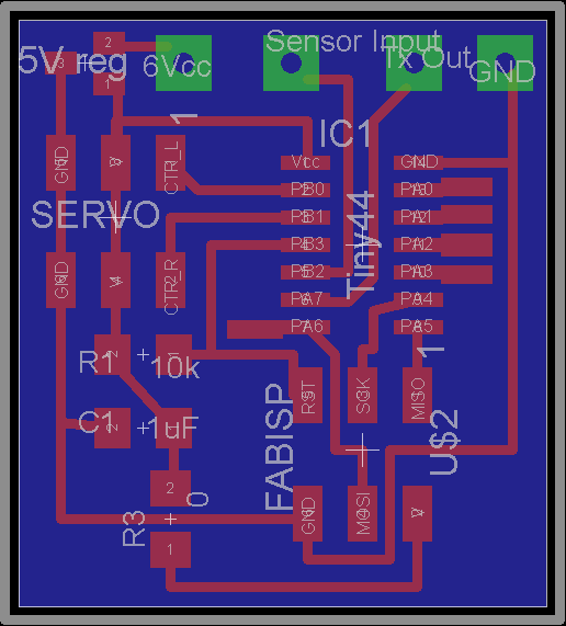
The circuit I designed to control the 2 motors is here:
Please ignore the connections and regulator at the top - these were for connections to other parts of the robot control.
You can see from the board that each servo has a Ground, Vcc, and Control connection - the Control is the PWM signal so connects diretly to the output pins of the Tiny44.
In order to find out the stop PWM for each motor I used an Arduino to make quick connections and write a quick script to get the motors moving.
int servoPin = 9;
int servoPosition = 1500; // position in microseconds
void setup() {
pinMode(servoPin, OUTPUT);
}
void loop() {
digitalWrite(servoPin, HIGH);
delayMicroseconds(servoPosition);
digitalWrite(servoPin, LOW);
delay(20); // wait 20 milliseconds
}
The results on the left show that the stop value is slightly different for each motor, in hindsight I could have made these the same by adjusting the potentiometer screw which would have made the programming more simple but I am a glutton for punishment!
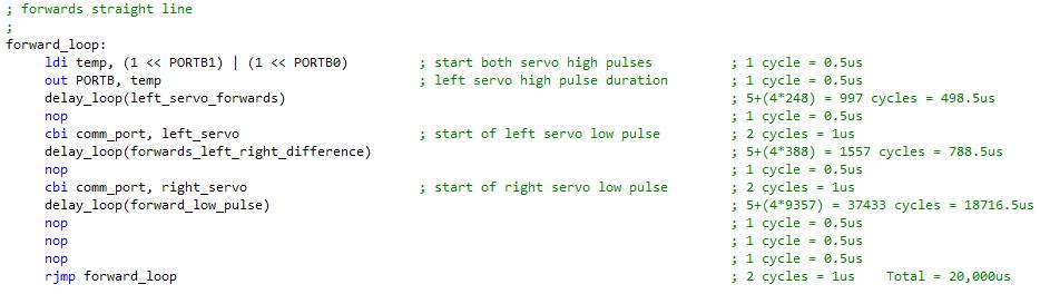
It did make the programming more complex as I had use different PWM signals for each servo. For this assignment I wrote a program that would make the vehicle move forwards, backwards, stop or turn. The forward procedure is shown here:
Assembly language allowed me to create procedures that produced an accurate 20ms period even with two different pulse widths. I did this with software PWM by turning pins on and off as I wanted to use the hardware PWM to feed my ultrasonic transmitter as this needs a constant accurate frequency.
 Please ignore the connections and regulator at the top - these were for connections to other parts of the robot control.
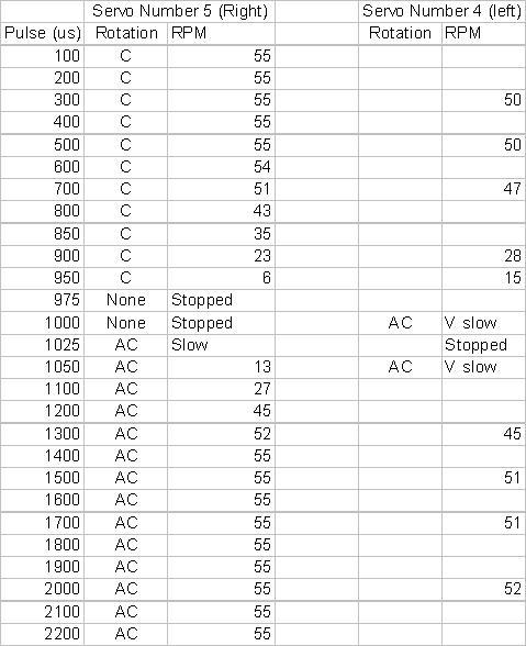 In order to find out the stop PWM for each motor I used an Arduino to make quick connections and write a quick script to get the motors moving.