This week's assignment was to measure something by adding a sensor to a microcontroller. I decided to make a proximity sensor using the Step Response circuit as there are a couple of projects I want to develop that will utilise this.
I based my circuit on Neil's step response ciruit but thinking ahead I also decided to connect an LED to an ouput pin on the controller so I could configure the microcontroller to send an output signal when a certain proximity was reached.
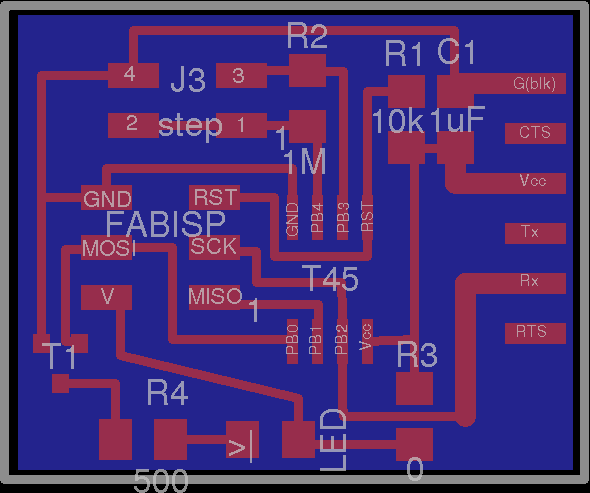
The board layout is shown below: Learning point: I designed this board quite a while before I wrote this up and for the life of me can't work out or remember why I have used the transistor to switch the output as they are both at 5V - this is why it is crucial to write up a project as you go along!!
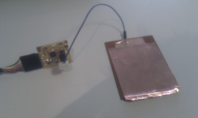
The physical result is here:
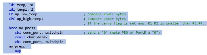
In order to program the microcontroller I took Neil's C program and re-wrote it in Assembly language. I used this to program the controller, connected the FTDI cable and then viewed the ouput using Neil's python program 'hello.step.45.py'. The initial response when moving my hand close to the electrode is shown below.
Referring to the top bar graph for the charge delay of 1us, the steady state was just over 600 and this dropped to about 570 when my hand was close. This was the most sensitive reading because it was on the steep slope of the step response curve for this RC circuit (closely followed by the 10us delay which was still on the steep slope but with the gradient just starting to drop off). As I wanted to use this as a proximity switch I added the following code to my program that sent a signal to the output pin when the ADC output for the 1us charge dropped below 590.