3D Scanning & Printing
3D Scanning
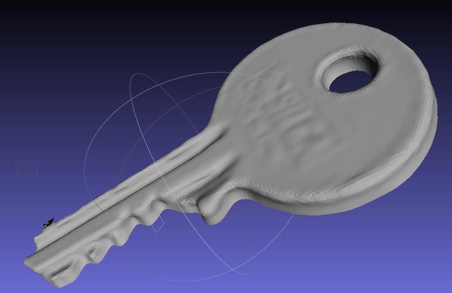
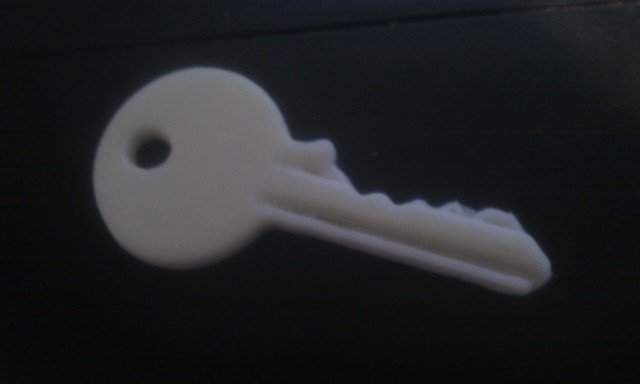
I decided to use the Modela to scan my object and after looking round for something insteresting to scan felt my keys in my pocket so thought they would make a good sample.
The scanning turned out to be the easy part. I used Dr Picza software that comes with the Modela and all i had to do was:
- Secure my key on the Modela bed using double-sided tape
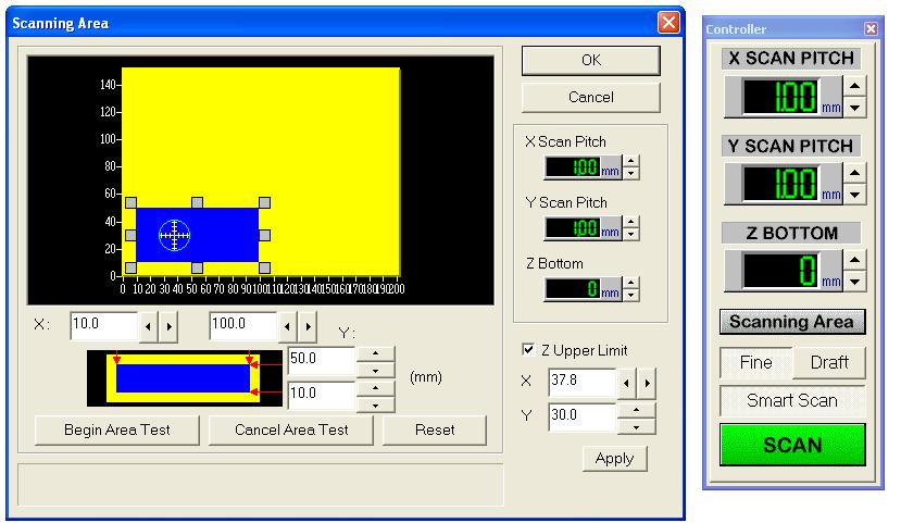
- Select the scanning area simply by measuring from the near left corner of the Modela bed and entering the corner coordinates
- Set the Z upper limit by dragging the target with the mouse cursor to the highest point on the key
- Click 'Apply' - the Modela will then move the probe to test the upper limit
- Set the Z-bottom to 0
- Choose scan pitch - I chose 0.1mm x 0.1mm
- Then click 'SCAN'
The scan took about 8 hours - this can be reduce by reducing the scan pitch but this in turn reduces the accuracy so it is a trade-off.
Post Processing
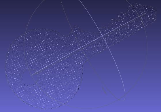
I found that if I exported an STL from Dr Picza for some reason all of the facet faces were aligned vertically along the length of the key. This resulted in a non-solid STL which was effectively a series of parallel fins. Therefore I saved the scan as an ASC point cloud.
I imported the point cloud into MeshLab and had to deselect 'Grid triangulation' or it created a mesh the same as described above.
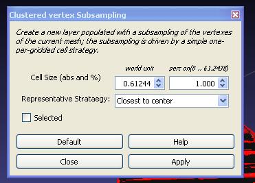
Once the vertices were imported I used 'Filter/Sampling/Clustered vertex Subsampling' with default values to simplify the model by reducing the number of vertices from 73,286 to 3,656.
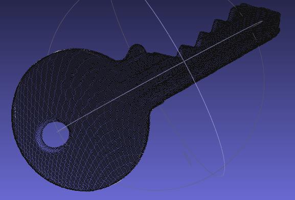
I then used 'Filters/Point Set/Compute normals form point set' to get the normals correct. Finally I used 'Filters/Point Set/Marching Cubes (APPS)' to create the surface mesh.
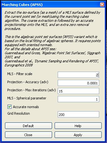
I left the grid resolution at 200 as increasing this greatly increased the model memory size.
This gave me a nice meshed surface except for two points
- There was a slight surface error at one point near the end of the key
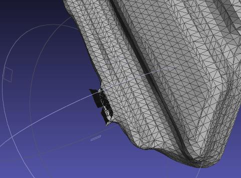
- The top of the key was just a hollow surface with no underside
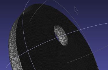
However, I decided to use NetFabb to fix these errors as I felt I had more control over what happened so I exported the result as an STL file
I opened the STL file in NetFabb and clicked the big red '+' to fix the errors. I zoomed in and manually deleted all of the erroneous triangles/facets around the first error leaving a hole in the mesh. I then clicked on ' Close all holes' which automatically filled the small error and created a new surface across the back of the key leaving a solid part. I then exported this as an STL and printed it on the 3D printer. This is the result:
3D Printing
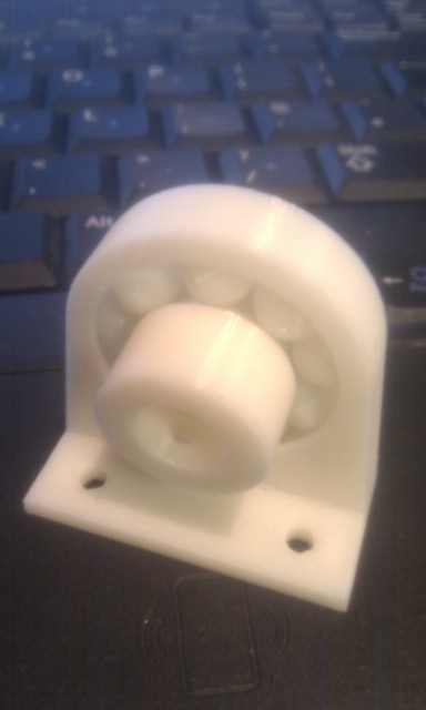 For the second part of this assignment I used Solidworks to design an axle bearing. I left 0.5 mm gap between the bearing and races in order to allow enough space for soluble material to be printed in the gaps. This was the result. The bearings actually move really smoothly and I am planning on using this as part of my autonomous vehicle for my final project.